NanoVG introduction
The NanoVG-Library offers a feature-rich API to scripts to draw various 2D shapes on the screen. This tutorial will introduce you to the API and how to draw shapes. This tutorial assumes you understood the basics of writing a plugin and the basics of Angelscript -- if you haven't already, check out the tutorial on plugin basics and the Angelscript overview before proceeding with this tutorial.
All code examples (and a bit more) are avaliable as a plugin for Openplanet here. Enable the plugin in the settings and go to the Scripts menu to navigate through the examples.
Table of Contents
Because this tutorial is quite lengthy, here is a short overview about the topics it addresses:
- Drawing a Rectangle
- Drawing a Triangle
- Colours and Gradients
- Bézier curves
Drawing a Rectangle
Let's start simple: our first goal is to draw a red rectangle somewhere on the screen. For this, we take a quick peek into the documentation and spot void nvg::Rect(float x, float y, float w, float h). This function lets us specify a rectangle to be coloured later by the top left corner of it (x and y) and its width (w) and height (w). Keep in mind you give the pixels where the top left corner is, so very large values might be perfectly fine on your 4K screen, but will be not visible on someone with a 720P screen!
Because we won't see yet the rectangle as it's only specified, not filled with anything, we need another function: nvg::FillColor(const vec4&in color). The function fills a previously specified shape or path with a colour. The vector color consists of how much red, green, blue and how opaque the shape shall be, with the values ranging between 0 and 1. As our rectangle is going to be red, we'll use this vector: vec4(1, 0, 0, 0.5): 100% red, 0% green, 0% blue, 50% opacity.
Note: The vec4 type is a vector with four components, assuming we want a vector (a, b, c, d), we bring it into the vec4 type by vec4(a, b, c, d). vec2 and vec3 behave the same, being types for vectors with two or three components. Here the vectors are used to define colours or positions on the screen.
Now we got almost everything we need to draw our first rectangle on the screen, so we can go ahead and write this into our plugin file:
void Render() {
    nvg::BeginPath();
    nvg::Rect(100, 100, 300, 150);
    nvg::FillColor(vec4(1, 0, 0, 0.5));
    nvg::Fill();
    nvg::ClosePath();
}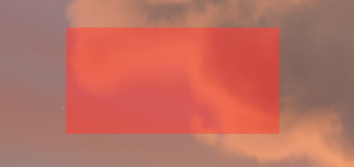
Where do all the other functions come from? Because we don't specify new objects every time we draw something new, we need to tell the API when our shape or path begins (nvg::BeginPath();) and when it ends (nvg::ClosePath();), so we don't have the wrong colour applied to the wrong shape et cetera. Additionally, nvg::FillColor only specifies the colour and opacity of our shape, to actually draw it onto the screen we need to add nvg::Fill();, otherwise it will not appear on the screen.
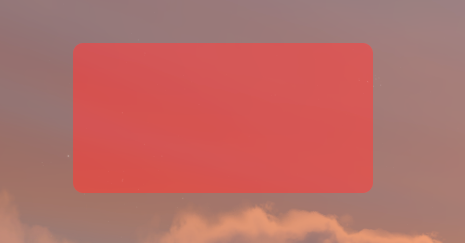
To spice things up a bit, we're gonna add rounded corners to our rectangle. This doesn't involve hocus-pocus using curves, because the API offers us a function for exactly that job: void nvg::RoundedRect(float x, float y, float w, float h, float r). The key difference is, that we need to pass another float to the function, r, which is nothing but the rounding radius for the window corners. So we change the line of code and write nvg::RoundedRect(100, 100, 300, 150, 10); instead, and suddenly our rectangle looks much more professional.
There are three more simple shapes to draw with NanoVG, experiment with them yourself:
Circles are drawn in a similar fashion, using void nvg::Circle(const vec2&in center, float r). They are specified by the x- and y-coordinates (vec2(x, y) building the vector for this purpose) of the center of the circle and the radius of the circle.
Ellipses are drawn similarly to circles, using void nvg::Ellipse(const vec2&in center, float rx, float ry). The center is the same as with circles, but the width of the ellipse is given by rx and the height is given by ry.
Rectangles with rounded corners, that vary, can be drawn using void nvg::RoundedRectVarying(float x, float y, float w, float h, float rtl, float rtr, float rbr, float rbl). The parameters for size and position are the same, but rtr to rbl describe the rounding radius for the individual corners with rtl being top left, rtr top right, rbr bottom right and rbl bottom left.
Note: If you only want the shapes be drawn, when the Openplanet overlay is opened, write your drawings into the RenderInterface() function, as the used Render() function is used to always draw onto the screen, even if the Openplanet overlay is currently closed. More information on the plugin functions you can use is avaliable here.
Drawing a Triangle
Unfortunately, rectangles and spheres do not offer us much flexibility, you can draw a lot you could draw on school tables onto the screen already, but polygons, arrows etc. cannot be drawn yet. To draw more triangles or such, we need to make use of paths. This works by drawing lines with an imaginary pencil on our canvas we can later use to draw a custom line or a custom shape with the line as the shape's outline. Moving the pencil with the API is similarly simple as drawing the lines by hand, except for it's way more precise as we can work with the single pixels instead of triangle rulers and squared paper.
To put our analogy of pencils into the actual code, we need to stare intensively at the API documentation again. We quickly spot functions called MoveTo and LineTo, which are exactly what we need. MoveTo moves our imaginary pencil to the coordinates we want to start drawing our lines, LineTo draws the actual lines between the corner points. With this, we know what we have to do now in code:
- Move to the starting point of the shape:
nvg::MoveTo(vec2(x, y)); - Draw lines on the canvas:
nvg::LineTo(vec2(a, b)); - Draw the last line ending at the starting point, to close the shape:
nvg::MoveTo(vec2(x, y)); - Fill shape or paint the outline, similar to before.
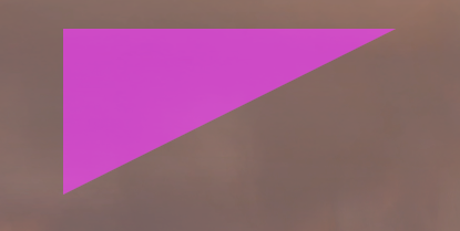
With this knowledge, we can draw a triangle now, where our rectangle used to be - remember, the rectangle's top left corner was at (100, 100) and it was 300 pixels wide, 150 pixels high, so with a bit of thinking we get this code to draw a triangle:
void Render() {
    nvg::BeginPath();

    nvg::MoveTo(vec2(100,100)); // top left corner
    nvg::LineTo(vec2(400,100)); // top right corner: 100 (x) + 300 (w), y remains
    nvg::LineTo(vec2(100,250)); // bottom left corner: x remains, 100 (y) + 150 (h)
    nvg::LineTo(vec2(100,100)); // back to top left

    nvg::FillColor(vec4(1, 0, 1, 0.5));
    nvg::Fill();

    nvg::ClosePath();
}
Reload the plugin and suddenly appears a pink triangle exactly where our red rectanlge used to be.
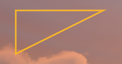
If we only want to draw the outline of the triangle, we can make use of the stroking functions instead of the filling functions (or use both to have a different outline than filling). A quick peek into the documentation shows us that the StrokeColor and Stroke functions can be used exactly the same as the filling functions -- the one takes a colour as a four-dimensional vector and the other just applies the colour to the outline. So, experiment with the functions yourself, to take our existing triangle and make it have a orange outline and no pink filling. Additionally, make the outline a bit more visible, making use of the void nvg::StrokeWidth(float size) function.
This is the solution to the task -- we can recycle a lot of code from the pink triangle:
void Render() {
    nvg::BeginPath();

    nvg::MoveTo(vec2(100,100));
    nvg::LineTo(vec2(400,100));
    nvg::LineTo(vec2(100,250));
    nvg::LineTo(vec2(100,100));

    nvg::StrokeColor(vec4(1, 0.5, 0, 0.5));
    nvg::StrokeWidth(5.5);
    nvg::Stroke();

    nvg::ClosePath();
}
To complete our knowledge on shapes and paths with straight lines, we got one thing left to try: Paths, that don't make up a shape. Fortunately, there's no magic involved here. The only difference to a path completing a shape and one that's just a random path is whether you add lines to return to the starting point or not. If we leave out the last LineTo-command in the previous drawing, we'll get a beautiful orange path on our screen. Try it out yourself!
NanoVG also lets you be lazy and does not require a path ending where the first line began for filling the space surrounded by the defined path. We can add our pink filling commands again, now that we left out the left line of the triangle and we'll see the triangle is back, it just lacks an orange line on the outside. Try it out yourself!
Note: Be careful, what the shape is of the polygon you want to draw. Convex polygons will always work fine to draw outline and to fill them with a colour or paint, as we seen in our triangle examples above. Concave polygons will work fine for drawing the outline, yet filling them might cause visual artifacts. Some parts of the shape will be filled twice, while the part, where the wedge is missing in the polygon will be filled, although it's not part of the polygon. In this case, you should split the polygon into two convex polygons to make it work properly. Try drawing a concave polygon as an exercise to see how it looks like and to exercise on working with the NanoVG API.
Colours and Gradients
Let's take on a different subject before we move on to drawing less pointy shapes: Colours and Gradients. So far we always have worked with flat colours defined by their red, green, blue and opacity component. This already lets us draw complex things that are recognizable and can be used for various widgets and stuff, yet gradients are something we cannot draw with flat colours. Imagine how cool a square in the center of the screen would be with a gradient from purple to yellow...
NanoVG offers us the option to create gradient "paints" which we can use then to paint our lines and shapes. We can chose between linear gradients, box gradients and radial gradients -- and if you played with these in an image manipulation tool of your choice before, what they look like and how they work in general should be very familiar for you. If you haven't played around with gradients before, opening up GIMP or another image manipulation tool of your choice and playing around with the gradient tool should give you quite a good idea, how these work and look like in the end.
Linear gradients create a colour fade between two points in a linear manner -- this way from one side of a shape to another you can get an evenly gradient to another side. Box gradients work by defining a box where all the gradient will be inside first - outside of the box everything will be coloured the one colour, inside of the box is a usually circular area of the other colour. The shape's size and radius can be given, as well as the length where the colours fade between the outside and inside area. If the given radius is smaller than the box, the shape will be a circle, if it's larger, it will be similar, but not round anymore. Radial gradients are similar to box gradients, however, they are given a center point around which the gradient will be drawn based on the radius from the center point, where the one colour ends being uniform and the radius, where the other colour begins being uniform.
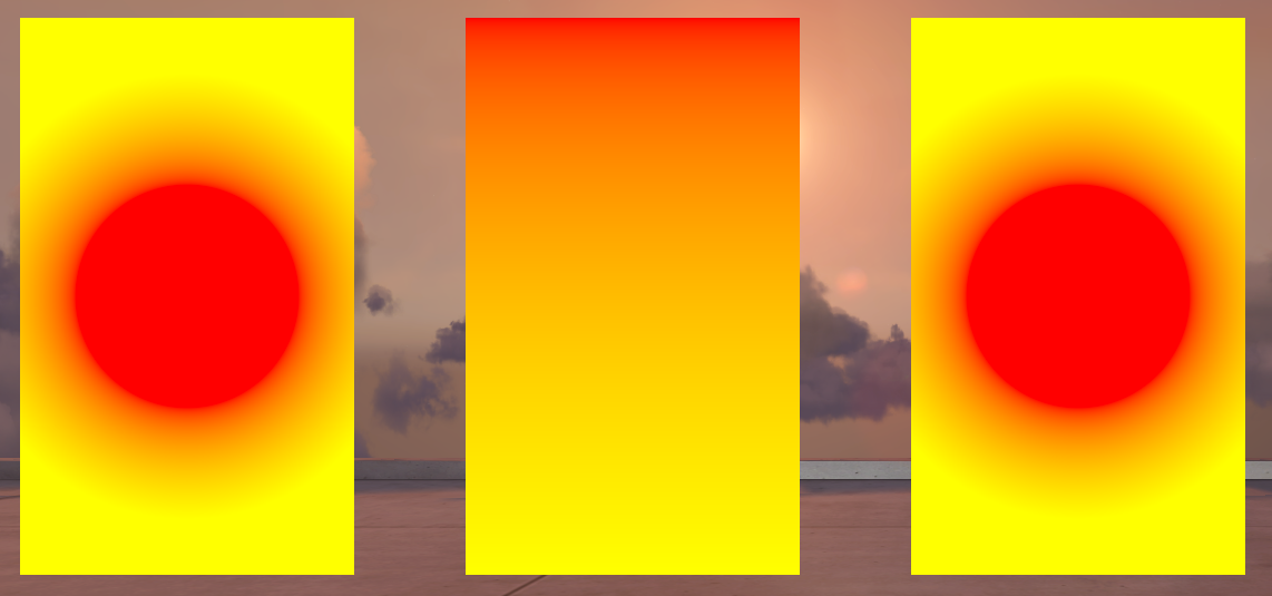
Let's take a look at an example with all three gradients:
void Render() {
    nvg::BeginPath();
    nvg::Rect(100, 100, 300, 500);
    nvg::FillPaint(nvg::BoxGradient(100, 200, 300, 300, 150, 100, vec4(1,0,0,1), vec4(1, 1, 0, 1)));
    nvg::Fill();
    nvg::ClosePath();

    nvg::BeginPath();
    nvg::Rect(500, 100, 300, 500);
    nvg::FillPaint(nvg::LinearGradient(vec2(500, 100), vec2(500, 600), vec4(1, 0, 0, 1), vec4(1, 1, 0, 1)));
    nvg::Fill();
    nvg::ClosePath();

    nvg::BeginPath();
    nvg::Rect(900, 100, 300, 500);
    nvg::FillPaint(nvg::RadialGradient(vec2(1050, 350), 100, 200, vec4(1, 0, 0, 1), vec4(1, 1, 0, 1)));
    nvg::Fill();
    nvg::ClosePath();
}
Note: If your screen resolution is smaller than 1280 x 720, you might need to adjust the values in this example to run it properly on your screen, as the three examples take up a space (from the top left) of 1200 pixels width and 600 pixels height!
First things first: Gradients are generated in code with the xyzGradient functions, which give back a variable with the type nvg::Paint, which you can then apply with nvg::FillPaint or nvg::StrokePaint to your shape or path. You can keep a variable to reuse a previously defined gradient several times, however, as we only use them once in this example, we won't do that. Also, our rectangles we use as a canvas to paint on are all 300 x 500 pixels large so we can compare how the results look like. To understand what parameter for the gradients do what, we will examine each function by its signature to understand why the results look like that.
Box gradient
The first rectangle is painted with a box gradient:
nvg::Paint nvg::BoxGradient(float x, float y, float w, float h, float r, float f, const vec4&in color1, const vec4&in color2)xandydefine the top left corner of the box,wandhthe width and height -- similar to rectangles- From the box size, the centerpoint is automatically determined, around which with the radius
rthe inner shape is made, which is filled withcolor1(here: red) fgives the distance of the colour fade outgoing from the inner shape, which will fade fromcolor1on the inside tocolor2on the outside -- the distance covers half of it's way on the inner circle and the other half on the outside of it- the rest of the box is coloured with
color2(here: yellow)
It's important to have the inner circle of the box gradient be smaller than the box itself, because otherwise NanoVG will cut the circle into pieces to make it fit, which might not be desirable for circle shaped gradients. Having NanoVG cut the circle into pieces to make it fit by chosing one legth of the box to be way shorter than the diameter is an easy way to get elipctically shaped gradients. However, we notice (and can see in code) that the inner circle has a radius of 150 pixels and the fade has a distance of 100, so overall we get a radius 200 pixels -- diameter 400 pixels, which is larger than our rectangle is wide! Unlike the too large inner circle of a box gradient, this works fine and can be used ad libitum. Also keep in mind that the gradient box may have different sizes than the shape which is painted. Experiment with the values of the box and of the rectangle to get a better understanding of how the box gradient behaves -- especially with a fade length of 0 and too small boxes and too large circle radiuses.
Linear gradient
The second rectangle is painted with a linear gradient:
nvg::LinearGradient(const vec2&in start, const vec2&in end, const vec4&in color1, const vec4&in color2)startandendare two-dimensional vectors containing the points where the gradient starts and ends - here it's the top left and bottom left corners of the rectanglecolor1is the colour at the starting point of the linear gradientcolor2is the colour at the end point of the linear gradient
Linear gradients work pretty intuitively, along a straight line there's the color fade -- the rest of the space will be filled with the start and end colours. Linear gradients are very simple and as such simple to use.
Radial gradient
The third rectangle is painted with a radial gradient:
nvg::RadialGradient(const vec2&in center, float inr, float outr, const vec4&in color1, const vec4&in color2)centeris a two-dimensional vector containing the center point of the radiuses that define the radial gradientinris the radius of the inner circle, which is filled withcolor1(here: red)outris the radius of the outer circle - the space between the inner and outer circle is filled with the gradient, the space outside of the outer circle is filled withcolor2(here: yellow)
Radial gradients achieve similar gradients as the box gradient function yields us -- in fact the values in the example are chosen so that both gradients look exactly the same. Radial gradients do not need a box and therefore the artifact with the cut-in-pieces circle does not appear with these.
Now that we've learnt how to colour things with gradients, we can make more complicated drawings regarding their colours. As an exercise you could draw a rainbow onto the screen with several rectangles filled with individual linear gradients for example or revisit the old shapes.
Bézier curves
So far we've dealt with colours and gradients and polygons, but we haven't dealt with the problem, how to make things nice and round. NanoVG offers us to use Bézier curves which are commonly used in computer graphics to draw round stuff, but before we get into working with them, we need to learn how they work as a concept.
Bézier curves, named after the French engineer Pierre Bézier, are one of the easiest way to draw nice and round paths. Generally, Bézier curves consist of a start and an end point and a set of control points defining the actual shape of the curve. Technically the curves are polynomials that are constructed with the help of the control points, in order to make the curve bend properly towards the control points, but still reach the end point in the end -- for a detailed explanation check out Wikipedia, we will only deal with the construction to get a rough idea, how Bézier curves are shaped when we work with them:
- Linear Bézier curves have no control points: they are just a straight line from the start point to the end point.
- Quadratic Bézier curves have a single control point. We can think of a straight line going from the start point to the control point and of another straight line from the control point to the end point -- we'll get an open triangle then. The Bézier curve we will get is a simple quadratic function passing through start and end points, that fits nicely into this open triangle.
- Cubic Bézier curves have two control points. They can be constructed based on quadratic Bézier curves: We can think of three straight lines between the start point and the first control point, between the first and second control point and between the second control point and end point and additionally we imagine three points at the beginning of each line. These three points are used to construct a quadratic Bézier curve, except for the points move by one percent over the line as the cubic Bézier curve we actually want is drawn by one percent. As such, a cubic Bézier curve takes a similar path to the path of two quadratic curves with same points for construction, but is significantly smoother in shape.
- Higher grade Bézier curves are not particularly useful, as we already see now that we can construct any curve with the help of cubic, quadratic and linear Bézier curves -- in fact, we can just ignore them in this tutorial since NanoVG only offers use to use these three types of Bézier curves.
Out of these elementary Bézier curve we can assemble curvy paths segment by segment, chosing the right type of Bézier curve one after another to draw it like we need it. If you are further interested in Bézier curves, there is a ton of good reading and learning materials on the subject by just using a search engine of your choice. Similarly like gradients, it is probably easier to mess around with Bézier curves in an vector graphics or image manipulation program, to interactively see how the line changes with the movement of control points.
Now that we know enough on how Bézier curves, we can look at how to create said curves with the NanoVG API.
Linear Bézier curves
Linear Bézier curves are pretty trivial to work with, we just use the already known nvg::LineTo function to draw straight lines. We pass the end point of the line to the function and it will save a straight line between two points to memory, we can later use to draw stuff with. The start point does not have to be specified, as we always first move our pencil to one of the points of our drawing and the start point of every new curve or path we draw is the current position of our pencil. As expected, no magic going on with linear Bézier curves.
Quadratic Bézier curves
Quadratic Bézier curves require us to stare closely at the API documentation again, spotting a function called nvg::QuadTo taking a control point c and the obligary end point pos. As explained before our start point of the curve is the current cursor position and we can pass the control point and end point to the function itself. For now, we'll just draw any quadratic curve - let's try it out:
void Render() {
    nvg::BeginPath();

    // start point: (100, 100)
    nvg::MoveTo(vec2(100, 100));

    // control point: (200, 400), end point: (300, 100)
    nvg::QuadTo(vec2(200, 400), vec2(300, 100));

    nvg::StrokeColor(vec4(1, 0.5, 0, 0.5));
    nvg::StrokeWidth(5.5); nvg::Stroke();

    nvg::ClosePath();
}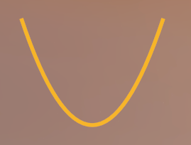
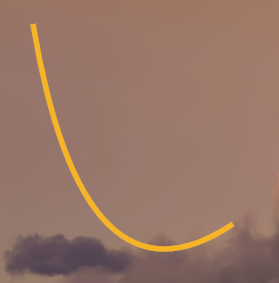
As we see, we get a path looking quite similar to a simple parabola, thanks to our choice of points, as start and end point are on the same height and the x-coordinates of all three points have the same spacing. If we choose a different set of points, we can get other parabola-esque lines -- change the control point to (150, 400) and the end point to (300, 300) to get a parabola rather reminding us of a tightening curve instead of something we remember from maths textbooks:
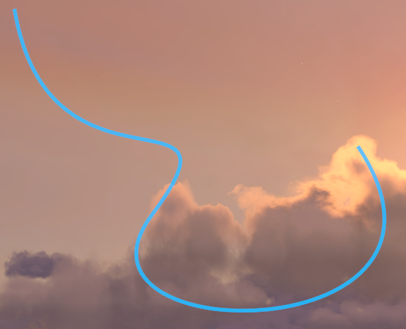
Of course, we can daisy-chain several quadratic Bézier curves to get fancy shapes:
void Render() {
    nvg::BeginPath();

    nvg::MoveTo(vec2(100, 100));
    nvg::QuadTo(vec2(150, 400), vec2(300, 300));
    nvg::QuadTo(vec2(450, 200), vec2(300, 400));
    nvg::QuadTo(vec2(150, 600), vec2(600, 600));
    nvg::QuadTo(vec2(800, 600), vec2(600, 300));

    nvg::StrokeColor(vec4(1, 0.5, 0, 0.5));
    nvg::StrokeWidth(5.5); nvg::Stroke();

    nvg::ClosePath();
}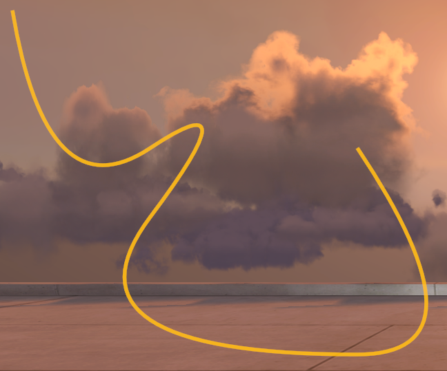
As always, we first move our cursor to (100, 100), to get away from the corners of the screen. Then we draw a quadratic Bézier curve with its control point at (150, 400) and its end point at (300, 300) and so on. If you play around with the values, you might notice you get ugly bends where end and start points of two curves meet. That's because we need to make sure the previous curve's control point, the start/end point and this curve's control point line up on a straight line. This way the curve points into the same direction at the end of the previous and at the start of our current curve and we do not get an ugly bend. Stare closly at the chosen values. For the first transition we go 150 px to the right each and 100 px to the top: (150, 400) -> (300, 300) -> (450, 200). For the second transition we go 150 px to the left and 200 px to the bottom: (450, 200) -> (300, 400) -> (150, 600). Look closely to see the same pattern in the third transition of the curves: We stay on the height of 600 px, as previous control and end points are both at that height so we can choose whatever x-coordinate for our next control point with the same height and we do not get a bend there.
Cubic Bézier curves
As explained earlier, cubic Bézier curves are to the most part two quadratic curves at once. To draw them onto our screen, we look once again at the documentation and spot a function called nvg::BezierTo, taking two control points c1 and c2 and the obligatory end point pos.
Let's try it out by drawing the first two bends of our path from the previous example with a single cubic Bézier curve:
void Render() {
    nvg::BeginPath();

    nvg::MoveTo(vec2(100, 100));
    nvg::BezierTo(vec2(150, 400), vec2(450, 200), vec2(300, 400));

    nvg::StrokeColor(vec4(0, 0.5, 1, 0.5));
    nvg::StrokeWidth(5.5); nvg::Stroke();

    nvg::ClosePath();
}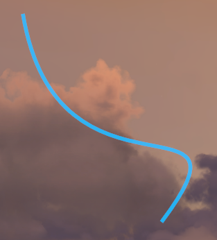
Oh no! While our cubic Bézier curve definitely passes through the old start point and the old end point, it looks way different. This becomes even more appearent, if we add back our old path consisting of quadratic curves. The bends aren't as sharp as with the quadratic curves, though that was to be expected, given that the cubic Bézier curve is a quadratic curve with moving construction points. However, you can move the cubic Bézier curve's control points farther away from the path, to get the same shape of a quadratic curve again. Experiment with the point placement, to get a cubic Bézier curve looking more similar to our previous two quadratic Bézier curves.
Of course we can still daisy chain cubic Bézier curves by adding another curve to our path. Lets add the second pair of quadratic curves as a single cubic curve to our current path:
void Render() {
    nvg::BeginPath();

    nvg::MoveTo(vec2(100, 100));
    nvg::BezierTo(vec2(150, 400), vec2(450, 200), vec2(300, 400));
    nvg::BezierTo(vec2(150, 600), vec2(800, 600), vec2(600, 300));

    nvg::StrokeColor(vec4(0, 0.5, 1, 0.5));
    nvg::StrokeWidth(5.5); nvg::Stroke();

    nvg::ClosePath();
}
We see even more deviation from our previous path (again, feel free to experiment at this point with the control point values), however, at least there's no ugly bend in the middle of the path! As with quadratic Bézier curves, cubic Bézier curves need to have the previous control point, the start/end point and the next control point in a straight line to not get ugly bends.
Additionally, we can make paths consisting of any curve type. To NanoVG it does not matter, whether it draws a straight line, a quadratic or cubic Bézier curve or whatever else it could draw. This way, we can draw any shape to our liking, without having to do weird hacky things, such as a completely straight cubic Bézier curve but can instead just use a straight line.
Note: We still have to be careful with shapes when filling them with paint or colour. NanoVG will automatically draw a straight line between the path's end and start point to create a fill-able shape, so non-completed shapes might only look odd when filled. However, concave shapes will cause problems when filling them: they will show the same symptoms as polygons trying to be filled will result in a big square in which the curve fits, that is filled with the given paint or colour. Again, you will want to split up the shapes into convex shapes in order to properly fill them, as convex shapes behave just as we want them to.
With this knowledge, you're good to go to draw about anything that you could draw on a two-dimensional canvas. By now we've learnt to draw simple shapes, draw any polygon, draw any bendy curvy shape and how to colour their filling or outline with flat colours or gradients. This means, you can finally unleash the Michelangelo in you and create either fancy art, or useful drawings and widgets on the screen. You could try your hand on creating a widget showing the steering, acceleration and braking input on the screen or a fancy RPM gauge.